Notes Chapter 14 Engboolean Logic
Introduction
– Boolean Logic, also known as boolean algebra was developed by mathematician “George Boole”.
– Later, Boolean logic helped in solving many big problems.
– These logics also helped in developing circuits.
– Complete logic is based on Yes or No which is also represented as True(T) or False(F).
– Computer system transmits its signals on high voltage or low voltage which can be denoted by true or false and with which we can develop it’s circuit.
– In this chapter we will learn thses logics.
Binary Values (Quantities)
– In our daily life, we need to take logical decisions where answers comes in either Yes (T) or No (F). For ex-
- Should I have tea?
- Should I see this movie?
- Sun rises in East? etc
- The decisions which results in Yes or No only are known as binary decisions.
- Values T and F are known as truth values.
- Boolean variables can only be either T or F.
- Indira Gandhi was the only lady Prime Minister of India (it results in true -T). Therefore it is a logic statement.
- What do you want to say?( it can not be result in T or F).
- Therefore it is not a logic statement.
Logical Operations
– These are of three types –
- AND
- OR
- NOT
- These are used to develop compound statement For ex –
- He prefers coffee not tea.
- He plays guitar and sitar.
- I watch TV on Sunday or I go for a movie.
- These are also used to join logical variables.
- For ex-
X NOT Y OR Z
Y AND Z OR X
Logical Operations
– Before proceeding for Operations we will get to know some features of logic statements. For ex –
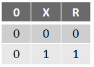
Statement– 1 : I want to have tea. Statement – 2 :Tea is ready.
now, develop a table with all its aspects.
(X) I want to have tea. T T F F
(Y) Tea is ready. T F T F
(R)(result) I have drink tea. T F F F
Now, if we create its truth table, its should be like-
– Truth Table is a table which contains all possible truth values of logical values along with all possible results.
– When all the results of a Truth Table are true (1) this condition is known as TAUTOLOGY and if all results are false (0) then this condition is known as FALLACY .
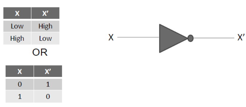
Logical Operators (NOT)
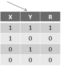
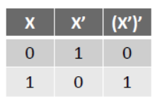
NOT operator is represented by applying ( ‘ ) or ( ¯ ) on an expression. For ex- X’ or X . This is a unary operator also known as complementation operator .
– 0’ = 1 and 1’ = 0
– Truth table and Venn Diagram for NOT operator is as under-
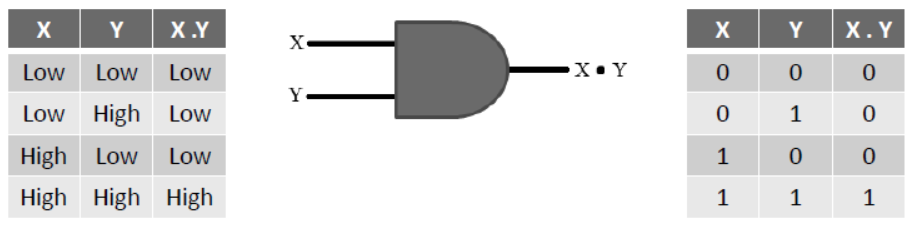
Logical Operators (AND)
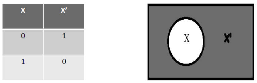
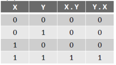
– AND operator is used by applying ( . ) between two variables. like X.Y
– It shows a very important operation of boolean algebra which is known as logical multiplication.
– X.Y is to be read as X AND Y.
– Rules of AND operation are-
0 . 0 = 0
0 . 1 = 0
1 . 0 = 0
1 . 1 = 1
– AND operator’s truth table and Venn Diagram are as under-
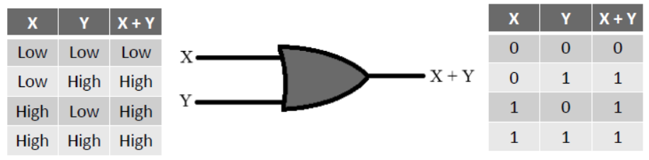
Logical Operators (OR)
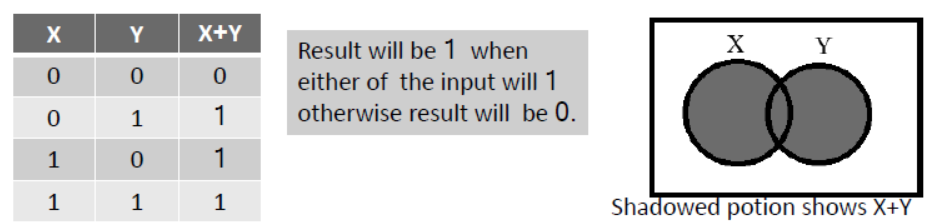
– OR operator is used by applying ( + ) between two variables. like X+Y
– It shows a very important operation of boolean algebra which is known as logical addition.
– X+Y is to be read as X OR Y.
– Rules of OR operation are-
0 + 0 = 0
0 + 1 = 1
1 + 0 = 1
1 + 1 = 1
– AND operator’s truth table and Venn Diagram are as under-
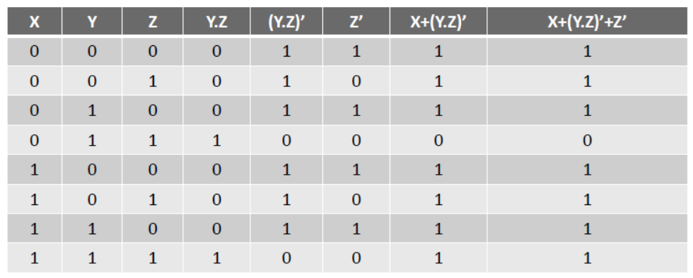
Evaluation of Boolean Expression using Truth Table
– To develop Boolean Expression, logical variables are used with logical operators. Truth table is used for its evaluation. For ex- X + (Y.X)’ + Z’ is a boolean expression and its truth table should be as follows-
Evaluation of Boolean Expression using Truth Table
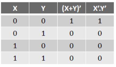
Prove (X+Y)’ = X’.Y’ using Boolean logic and truth table-
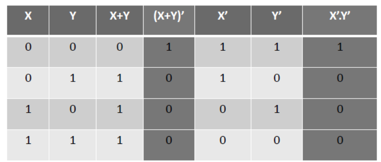
By comparing (X+Y)’ and X’.Y’ it is proved that both the values are same.
Basic Logic Gates
– When Shannon used boolean logic in switching circuit of telephone then Engineers realized that boolean algebra can also be used in computer electronics. In computers, logic gates are used to complete boolean operations.
– A Gate is a basic Electronic Circuit used to develop an output signal by passing one or more input signal(s).
– A Gate is a kind of two-state digital circuit because its input or output are either low voltage (i.e. 0) or high voltage (i.e.1).
– Gates are also known as logic gates because they can coordinate with boolean logic.
– Logic gates are of three types–
1. Inverter (NOT Gate)
2. OR Gate
3. AND Gate
Inverter (NOT Gate)
– NOT gate takes one input and produces one output.
– Its output is exactly opposite to its input.
– It is called NOT gate because its output is not similar to its input.
– Its output is also called as complement(opposite) of input.
– Truth table and diagram of Not gate are as under-
OR Gate
– OR gate takes two or more inputs and produces one output.
– Its output is logical sum of passed inputs.
– It produces high voltage output on any one high voltage input. It produces low voltage output only when all the inputs are of low voltage.
– OR Gate Truth table and diagram are as under-
–This gate work for more than two input signals in similar manner
AND Gate
– AND gate takes two or more inputs and produces one output.
– Its output is logical multiplication of passed inputs.
– It produces low voltage output on any of the input signal as low voltage input. It produces high voltage output only when all the inputs are of high voltage.
– AND Gate Truth table and diagram are as under-
– This gate work for more than two input signals in similar manner.
Boolean logic-Basic Postulates
– Boolean algebra is a kind of mathematical system because of which it is based on some fundamental laws which are known as basic postulates. Which are as follows- –
I. If X ≠ 0 then X = 1 and if X ≠ 1 then X = 0
II. OR Relations (logical addition)
- 0 + 0 = 0
- 0 + 1 = 1
- 1 + 0 = 1
- 1 + 1 = 1
III. AND Relations (logical multiplication) - 0 . 0 = 0
- 0 . 1 = 0
- 1 . 0 = 0
- 1 . 1 = 1
IV. Complementary Rules: - 0’ = 1
- 1’ = 0
Principle of DUALITY
– It is very important concept of boolean logic. A boolean relation can be drived by other boolean relation if we follow following rules-
1. Every OR signal (+) is replaced by AND signal (.).
2. Every AND signal (.) is replaced by OR signal (+).
3. Every 1 is replaced by 0 and every 0 is replaced by 1.
– The received expresseion will be dual expression of original expression. For ex-
– Dual of 0 + 0 = 0 will be 1 . 1 = 1
– Dual of 0 + 1 = 1 will be 1 . 0 = 0
– Dual of 1 + 0 = 1 will be 0 . 1 = 0
– Dual of 1 + 1 = 1 will be 1 . 1 = 1
Main Concepts of Boolean Algebra
I. Properties of 0 and 1
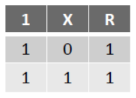
I. 0 + X = X
II. 1 + X = 1
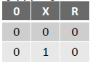
III. 0 . X = 0
IV. 1 . X = X
0 + X = X
1 + X = 1
0 . X = 0
1 . X = X

II. Indempotence Law –
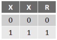
(a) X + X = X
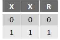
(b) X . X = X
Main Concepts of Boolean Algebra
III. Involution – (X’)’ = X
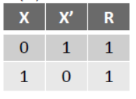
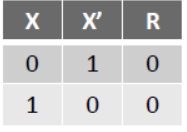
IV. Complementarity Law –
(a) X + X’ = 1
(b) X . X’ = 0
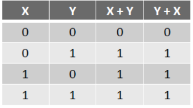
V. Commutative Law –
(a) X + Y = Y + X
(b) X . Y = X . Y
Main Concepts of Boolean Algebra
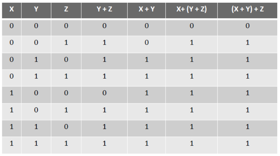
VI. Associative Law –
(a) X+(Y+Z) = (X+Y)+Z
Main Concepts of Boolean Algebra
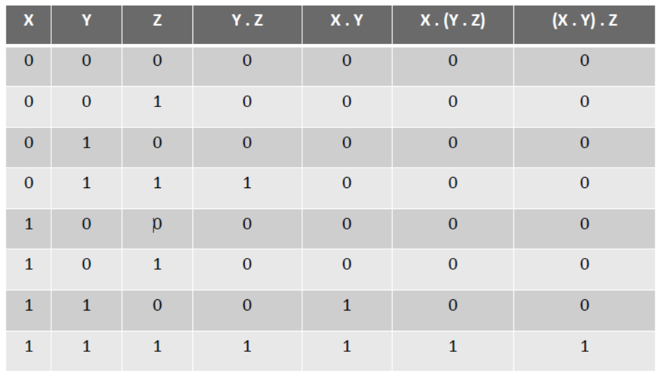
VI. Associative Law –
(b) X . (Y . Z) = (X . Y) . Z
Main Concepts of Boolean Algebra
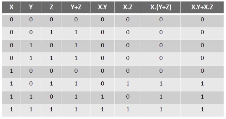
VII. Distributive Law –
(a) X . (Y + Z) = X.Y + X.Z
Main Concepts of Boolean Algebra
VII. Distributive Law –
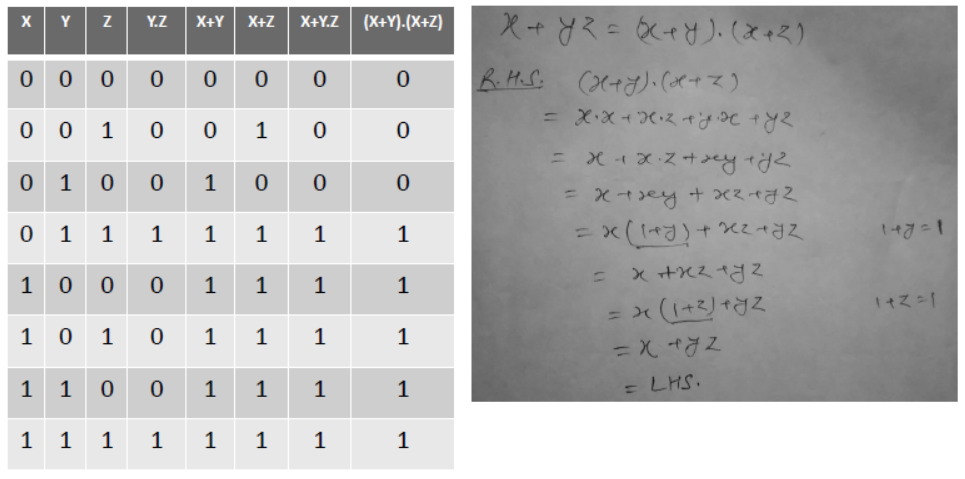
(b) X + Y.Z = (X + Y) . (X + Z)
Main Concepts of Boolean Algebra
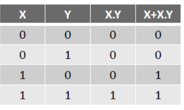
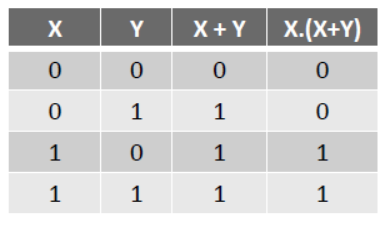
VIII. Absorption Law –
(a) X + X . Y = X
(b) X . (X + Y) = X
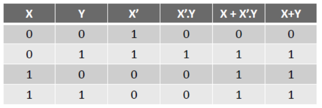
IX. Other rules (Third Distributive Law)
X + X’.Y = X + Y
Main Concepts of Boolean Algebra
X. DEMORGAN’s Law –
(a) (X+Y)’ = X’ . Y’
(b) (X.Y)’ = X’ + Y’
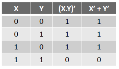
You can prove a law with the help of truth table and can also be proven mathematically.
Sum of Product : ABC, XY, X’YZ’ etc
Product of Sum : A+B+C, X+Y’+Z’ etc
Minimization of Boolean Expression algebraically
- Minimize the expression- AB’CD’ + AB’CD +ABCD’ + ABCD Solution:
AB’CD’ + AB’CD +ABCD’ + ABCD
= AB’C(D’+D)+ABC(D’+D)
=AB’C + ABC
= AC (B’+B) = AC.1 = AC
Other Logic Gates
– There are some derived gates also besides AND, OR, NOT Gates. Like-
NOR, NAND, XOR, XNOR Gates.
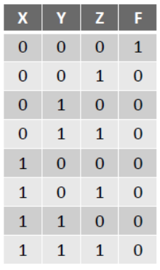
NOR Gate:
There is two or more input signals and one output signal in NOR gate.if all input signals are 0 (low) then output signal will be 1 (high).
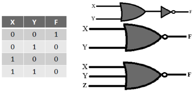
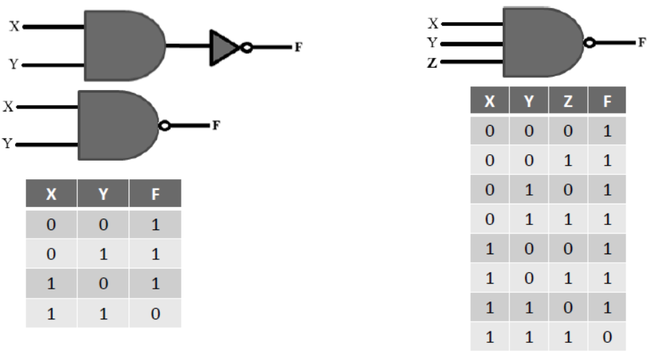
NAND Gate
- There is two or more input signals and one output signal in NAND gate.if all input signals are 1 (high) then output signal will be 0 (low). It is also known as universal gate because fundamental gates can be retrieved with its help.
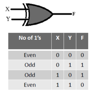
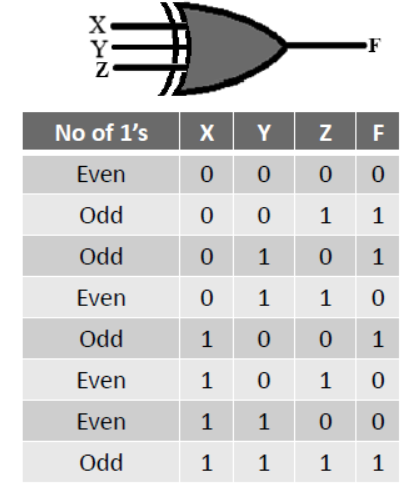
XOR Gate
- XOR Gate produces 1 (high) when inputs are not at equal logic level. It is also known as universal gate because fundamental gates can be retrieved with its help.
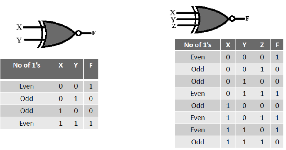
XNOR Gate
- XNOR Gate produces 1 (high) when the inputs are identical
(both 1’s or both 0’s).
Assignment
1. Prepare AND, NOT and OR gate and their circuit diagram by NAND gate.
2. Prepare AND, NOT and OR gate and their circuit diagram by NOR gate.
3. Prepare logic circuit for the following-
I. F(A,B,C) = AB + AC’ + A’B’C
II. F(X,Y,Z) = (X+Y) . (X’+Z’) . (Y+Z)