Chapter 13 Magnetic Effect of Electric Current Class 10 Science Notes
Students should read Chapter 13 Magnetic Effect of Electric Current Class 10 Science Notes provided below. These notes have been prepared based on the latest syllabus and books issued by NCERT, CBSE and KVS. These important revision notes will be really useful for students to understand the important topics given in the chapter Magnetic Effect of Electric Current in Class 10 Science. We have provided class 10 science notes for all chapters.
Revision Notes Chapter 13 Magnetic Effect of Electric Current Class 10 Science
Chapter 13 Magnetic Effect of Electric Current is an important chapter in Class 10 Science. The following notes will help you to understand and easily learn all important points to help you score more marks.
IMPORTANT TERMS & CONCEPTS
The word magnet is derived from the name of an island in Greece called ‘magnesia’, where the stone of magnetic ore (black ore of iron Fe3O4, called magnetite) was found. In their local language, Greed called this stone, ‘lodestone’.
Magnetic of electric current is derived by Oersted experiment which conclude that electricity and Magnetism are linked with each other.
1. Oersted’s experiment: In 1820, Hans Christian Oersted, professor of Physics at Copenhagen discovered that there exists a relationship between electricity and magnetism. He observed that acompass needle got deflected on passing an electric current through a metallic wire placed horizontally near it. This shows that current carrying conductor behaves as a bar magnet. This can be explained by the following activity.
Magnetic of electric current can be studied is three aspects :
1.Bar magnet
2.Moving effect of moving charge
3.Electric effect of moving magnet
Bar magnet has a magnetic field in surrounding region.
2. Properties of Magnetism:
• It has both magnitude and direction
• Formed continuous closed curve (inside N to S and Outside S to N)
• Crowded field lines represents strong field
• Never intersect with each other
• Tangent at a point gives the direction of magnetic field at that point.
3. Magnet: A substance that possesses the property of attracting certain other substance such as iron, nickel, cobalt, etc. is known as magnet.
4. Types of magnet :
Natural Magnet: The substance which is found in nature and has an attractive property to attract iron and some of its ores is known as natural magnets. It has an irregular shape.
Example: lodestone (magnetite), basalt. The earth itself acts as a giant natural magnet.
5. Artificial Magnet: They are generally made from special iron or steel alloys which are usually magnetized electrically. Therefore, the magnet produced from magnetic material is called artificial magnet. It can be shaped in any desired shape and size such as bar shape, U-shape and circular shape. Artificial magnets have a wide variety of applications.
6. Use of Magnet:
The various uses of magnet are:
I. In children’s toys
II. In radio and stereo speakers
III. On hard disc and floppies for computers
IV. In refrigerator and other doors, to snap them close
V. In audio and video cassette tapes
VI. In medical therapy
VII. An MRI (Magnetic Resonance Imaging) scan uses a magnetic field of powerful magnets to create picture of organs and structures inside the human body.
VIII. In production of electricity.
7. Magnetic Substances: The different metallic substances from which magnets can be made are known as magnetic substances. Example: Iron, nickel, cobalt, Alnico.
8. Non-magnetic Substances: The substances which do not possess the magnetic properties are called non-magnetic substances. Example: Aluminium, brass, copper, wood, glass, etc.
9. Basic law of magnetism:
I. Every magnet attracts a small piece of magnetic substance towards it. The ends of a bar magnet where attraction is maximum are called poles of the magnet.
II. A freely suspended magnet aligns itself along the north south direction. Geographic north seeking end of the magnet is called north pole. The other end of a suspended magnet that
points towards geographic south is called south pole.
III. Like poles repel each other and unlike poles attract each other.
IV. Magnetic poles always exist in pair. They can never be separated I.e., magnetic monopole does not exist.
10. Magnetic Compass: The freely suspended magnetized needle pivoted on the pointed nail enclosed in a small glass case is called magnetic compass. It always rests in north-south direction. Normally the north pole of the needle is painted red. So, with the help of needle, geographical north and south direction can easily be identified.
11. Magnetic Field:
• The space or region surrounding a magnet, in which another magnet experiences a force of attraction or repulsion is called magnetic field.
• The magnetic field around a bar magnet can be detected by getting the deflection of compass needle placed near it. Magnetic field has both direction and magnitude. Its direction is the direction in which north pole of the compass needle moves.
• The strength of magnetic field at a point is defined as the force experienced by the unit magnetic north pole when placed at that point. The unit of magnetic field strength is weber/m2 or tesla.
12. Magnetic Lines of force (or Magnetic field lines): The presence and influence of a magnetic field can be visualized by magnetic lines of force. It is defined as the path along which the unit north pole (imaginary) tends to move. The following activity shows the pattern of magnetic field lines around a bar magnet.

Place a bar magnet at the centre of a cardboard. Sprinkle some iron fillings on the cardboard.
Now tap the board gently. We observe that iron fillings arrange themselves in a pattern as shown in the figure. The lines along which the iron fillings align themselves represent magnetic field lines. It determines both the relative strength and the direction of magnetic field. Another way of drawing the magnetic field lines around a bar magnet is shown below.
13. Properties of Magnetic Field Lines:
I. Magnetic field lines are closed continuous curves. They come out from the north pole of a bar magnet and go into its south pole. Inside the magnet they move from south pole to north pole.
II. A tangent drawn at any point on the magnetic field lines gives the direction of magnetic field at that point, i.e., compass needle align itself along the tangent to the lines of force at that point.
III. The magnetic lines of force do not intersect (or cross) one another. If they do so then at the point of intersection, two drawn tangents at that point indicate that there will be two different directions of the same magnetic field, i.e., the compass needle points in two different directions which are not possible.
IV. The region where the magnetic field lines are crowded (converging), the field is stronger andwhere they are apart from each other (diverging), the field is weaker.
14. Magnetic field line surrounding region visualized by magnetic field lines exert a force on current carrying conductor placed in it which depends on following factor :
• Current
• Length of conductor in magnetic field
• Magnetic field strength
• Angle between conductor and magnetic field.
15. Magnetic Lines of force between two magnets:

16. Sources of Magnetic Field:
I. A natural magnet or an artificial magnet,
II. A current carrying straight conductor or circular conductor or solenoid,
III. A moving charge and,
IV. Changing electric field, are the various sources of magnetic field.
17. Magnetic Field due to a Current Carrying Straight Conductor: The field lines is in the form of concentric circles around it with centre on wire.
Oersted’s experiment proves that the current carrying conductor always produces a magnetic field around it. This causes the deflection in magnetic needle placed near it.
Straight conductor has direction which is given by Right-Hand Thumb Rule
18. Right-Hand Thumb Rule: This rule is used to find the direction of magnetic field due to a straight current carrying wire. It states that if we hold the current carrying conductor in the right hand in such a way that the thumb is stretched along the direction of current, then the curly finger around the conductor represent the direction of magnetic field produced by it. This is known as righthand thumb rule.
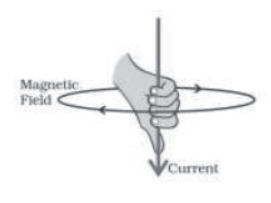
Direction of Field Lines due to current carrying straight conductor as shown in figure.
19. Magnetic Field due to a Current Carrying Circular Coil:
Circular and concentric field near the coil .Near the centre field lines are straight and parallel at centre field is perpendicular to the plane of the coil.
It is directed outwards for the anticlockwise flow of current while inwards for clockwise current flow.
A current carrying circular coil behaves like a magnet. The direction of magnetic field of every section of the circular loop can be found by applying the right hand thumb rule. The field lines will be in the same direction within the circular coil. Mapping of magnetic field lines produced by the current carrying circular coil can be easily done by doing the following activity.
20.

Note: Direction of current in the back face of the current carrying circular coil will be in opposite direction to that of the front face towards your side of that coil.
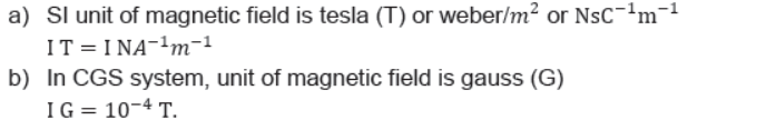
21. Unit of Magnetic Field:
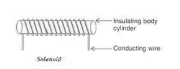
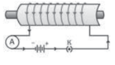
22. Solenoid:
Behaves like a magnet .Inside a solenoid there is uniform magnetic field .A coil of many circular turns of insulated copper wire wound on a cylindrical insulating body (i.e., cardboard etc.) such that its length is greater than its diameter is called solenoid.
A solenoid is shown in figure:
Magnetic field in solenoid depends upon
• Number of turns per unit length
• Current
• Nature of core material inside it.
Some important facts:
I. When current is flowing through the solenoid, it behaves like a bar magnet.
II. One end of a current carrying solenoid behaves as north pole while the other end acts as a south pole.
Note: the solenoid has Polarity at its end .The polarity at the ends of a solenoid can be determined by the following ways:
a) Using bar magnet: Bring the north pole of a bar magnet towards the one end of freely suspended current carrying solenoid. Repulsion indicates that the face of the solenoid is north pole while attraction shows that the face will act as south pole.
Note: Same result will also be obtained by using magnetic compass needle.
b) Using clock face rule: If the direction of current through the end of a solenoid facing towards you is clockwise, then the face has south polarity while the other end having anticlockwise current will acts as north pole.
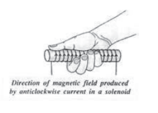
c) Direction of Magnetic Field: Imagine the current carrying solenoid in your right hand such that the fingers are curled in the direction of current, then the extended thumb gives the direction of magnetic field as shown in the figure.
Note: Solenoid can be used to form Permanent magnet (Steel core)
Features of Magnetic field lines:
1. The magnetic field lines due to a current carrying solenoid resemble exactly with those of a bar magnet with the fixed polarities at its ends.
2. It acquires the directive and attractive properties of a bar magnet.
3. Outside the solenoid field lines emerges from the north pole and enter into its south pole.
Inside the solenoid, they move from south pole to north pole. Thus they from continuous closed cures.
4. Since the current flowing through each turn has the same direction, the direction of magnetic field produced by each turn is also same. So effective magnetic field in the interior of a solenoid.
5. The field inside the solenoid is in the form of parallel straight lines which are very close to each other. This indicates that the strength of magnetic field is same at all the points inside the solenoid.

6. Whenever the current is flowing through the coils of a solenoid, magnetic field is produced inside it and becomes zero when the current is switched off.
7. When the direction of current through the solenoid is reversed, its polarity is also reversed.
8. The strong and uniform magnetic field inside the solenoid is used to magnetise the pieces of magnetic materials like soft iron.
9. The pattern of the magnetic field lines around the current carrying solenoid is shown in figure.
23. Electromagnet: It works on the magnetic effect of current. The temporary magnet which retains its magnetism as long as the current passes through the coil wounded around a piece of soft iron core is known as electromagnet.
The strength of an electromagnet depends upon
I. Magnitude of current flowing through the solenoid as
II. Number of turns in the solenoid, as B∝I
III. Closeness of the turns and B∝N
IV. Length of the coil as B∝ I/l
Advantages of an electromagnet:
I. It produces very strong magnetic field.
II. Its magnetism lasts as long as current flows through it. So, it is a temporary magnet.
III. The strength of electromagnet can be controlled by varying either the number of turns or the current flowing through it.
IV. Polarity of electromagnet can be interchanged by changing the direction of current flowing through the solenoid.
Uses of electromagnets:
I. To separate magnetic substances from non-magnetic substances.
II. Electric cranes use the electromagnets to lift and shift heavy iron loads for loading and unloading purpose.
III. Used in electric bells, telephones receivers, microphones, loudspeakers, electric relay, television, etc.
IV. Hospitals use electromagnets to extract iron or steel bullets from the human body.
Permanent magnet: Solenoid can be used to form Permanent magnet (Steel core) . The piece of material which retains its magnetism even after removing the magnetizing field is known as permanent magnet.
Formation of permanent magnet electrically:
The permanent magnet can be formed by placing hard steel such as cobalt steel. Tungsten steel or carbon steel inside a strong uniform magnetic field, produced by a current carrying solenoid.
The magnet so obtained is called permanent magnet. Such materials have a property to retain their magnetism even after the current in the solenoid is switched off. Now a day permanent magnets are made from Alnico (an alloy of aluminium, nickel, cobalt and iron) and Nipermag (an alloy of aluminium, iron, nickel, and titanium).
Characteristics of permanent magnet:
I. The polarity of permanent magnet cannot be changed.
II. Magnetic field strength of the permanent magnet cannot be changed.
III. It is not easy to demagnetize the permanent magnet as it can be demagnetized either by heating or throwing it again and again on the hard floor.
Uses of permanent magnet:
I. In measuring devices such as ammeter, voltmeter, galvanometer and speedometer, etc.
II. In electrical devices such as loudspeakers, microphone, electric clocks, etc.
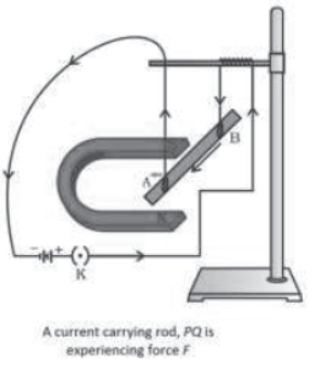
24. Force on a linear current-carrying conductor in a magnetic field:
We have learnt that current carrying conductor produces a magnetic field which exerts a magnetic force on the magnetic needle placed near it and thereby deflecting the needle. The question arises, is reverse of it also true? French scientist, Andre Marie Ampere suggested that magnetic field produced by a magnet exerts an equal and opposite force on a current carrying conductor. This force causes the conductor to move from its rest position as shown in figure It is found that:
I. Force is maximum when current carrying conductor is placed perpendicular to the direction of magnetic field and maximum displacement occurs.
II. Current carrying conductor does not experience any force when it is placed parallel to the direction of magnetic field. This is the basis of determining the direction of magnetic field.
III. Direction of force acting on a current carrying conductor gets reversed if the direction of
a) Current flowing through the conductor is reversed or b) Magnetic field is reversed.
The general equation for the force (F) on a current (I) carrying conductor of length (l) in a magnetic field (B) is given by F=Il Bsinθ. Where θ is the angle made by conductor with magnetic field (B).
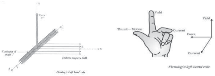
The direction of force acting on a current-carrying conductor in a magnetic field can be found by using Fleming’s left-hand rule.
25. Fleming’s Left Hand Rule: According to this rule, stretch the thumb, forefinger and middle finger of your left hand such that they are mutually perpendicular to each other. If the forefinger points in the direction of magnetic field (B) and middle finger points in the direction of current (I), then the thumb will point in the direction of motion or the force acting on the conductor as shown.
This rule is applied only when direction of both current and magnetic field is at right angle to each other.
26. Electric Motor: The device which converts electrical energy into mechanical energy to get the rotational motion is called an Electric motor.
Principle: It works on the principle of force experienced by a current carrying conductor in a magnetic field .The two forces act on the arm of opposite sides of rectangular coil in a uniform magnetic field are equal and opposite since they act in different lines ,they bring rotational motion .
Construction: It consists of a rectangular coil PQRS of insulated copper wire suspended in a uniform magnetic field. The ends of a rectangular coil are connected to the two copper metallic split rings ‘C’ and ‘D’ called commutator. It rotates along with the coil. The function of commutator is to reverse the direction of current through the coil after every half rotation. The external source such as battery sends the current to the coil through key and conducting stationary bushes ‘X’ and ‘Y’ slides over the split rings ‘C’ and ‘D’ respectively.
Working: Consider at the beginning, the arms ‘PQ’ and ‘RS’ are perpendicular to the direction of applied magnetic field:
a) Initially: let the current in the coil flows along the path PQRS. Then according to the Fleming’s Left hand Rule, a downward force acts on the arm ‘PQ’ pushes it downwards and an upward force on arm ‘RS’ pushes it upwards. These forces cause the coil to rotate in anticlock-wise direction about its own axis as shown in figure (a).

b) After completing half rotation, the position of split rings interchanges due to which direction of current in the coil gets reversed and current flows along the path SRQP. Again according to Fleming’s Left Hand Rule, the force acting on the arms ‘PQ’ and ‘RS’ also get reversed.
This makes the coil to rotate and complete the next half cycle of rotation in the same direction.
Thus, the interchanging of split rings at each half turn makes the coil to rotate continuously in the same direction as long as the current is passing through it.
The power of electric motor can be enhanced by
I. Using an electromagnet in place of permanent magnet,
II. Increasing the number of turns in the coil and
III. Using a soft iron core on which the coil is wound.
These electric motors are used in electric fans, water pump, tram cars, mixer, refrigerators, washing machines, computers, DVD players, etc.
27. Electromagnetic Induction:
It is relative motion between magnet and coil .The changing magnetic field linked with the coil causes current to flow through it. This current is called induced current and the phenomenon is known as electromagnetic induction. If the circuit is open, it will leads to formation of induced e.m.f While if the circuit is closed then an induced current is produced that has direction give by Flemming right hand rule .
For example. When a north pole of a magnet approaches the coil whose ends are connected to a galvanometer, its needle gets deflected in a particular direction. This shows that the current is induced in the coil and is in anticlockwise direction. This means the face of the coil towards magnet acts as north pole. If north pole moves away from the coil, same face will now acts as a south pole, as needle has deflected in opposite direction.
Current in coil is also induced when south pole of the magnet approaches the coil or pulled out from the coil. When magnet is stationary with respect to coil, no current is induced in the coil. The magnetic field lines of force passing through a coil is called magnetic flux, which can be changed by one of the following ways:

a) Relative motion between the magnet and the coil i.e.,
I. By moving a coil in the magnetic field.
II. By changing the magnetic field around the coil.
III. By rotating the coil in the magnetic field.
b) Change the current
I. In the neighboring coil, or
II. In the same coil.
Thus, an induced current flows through a closed circuit as long as the magnetic field linked with it keeps changing.
c) The value of induced current depends upon:
I. Strength of changing magnetic field: Motion of powerful magnet produces a large induced current.
II. Speed of magnet: faster the motion of magnet more will be the induced current.
III. Number of turns of the coil: more the number of turns in the closed coil, larger will be the induced current.
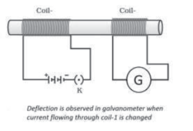
28. Induced current without magnet: Two circular coils of insulated thick copper wire having different number of turns are placed near each other or wound over a non-conducting cylindrical roll as shown. Change the electric current through the primary coil (i.e. coil-1) either by starting or stopping or by varying the current with the help of rheostat, it is found that whenever the current through primary coil is changed, a potential difference is induced in the secondary coil (i.e.coil-2). The reason is that when the current in the primary coil changes, the magnetic field is produced around it. Some magnetic field lines will pass through the secondary coil also. Therefore, due to change in magnetic field lines around the secondary coil, a potential difference is induced in it and hence current is induced.
So, as long as the current in the primary coil is changing, an induced current flows in the secondary coil. A transformer used to step-up or step-down the voltage is based on this principle.
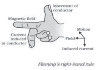
29. Fleming’s Right Hand Rule for direction of induced current: According to this rule if we stretch the thumb, forefinger and middle finger of right-hand in mutually perpendicular directions such that the forefinger indicates the direction of magnetic field and thumb is along the direction of motion of the conductor, then the idle finger will point in the direction of the induced current.
30. Electric Generator: A device used to convert mechanical energy into electrical energy is called an electric generator. Principle: It is based on the principle of electromagnetic induction. It’s direction given by Fleming’s Right-Hand-Rule.
Types of electric generator: Electric generators are two types:
I. Alternating Current generator (AC generator)(induces electric current)
II. Direct Current generator (DC generator). Both the generators work on the same principle i.e., electromagnetic induction.(indices direct current)
31. Parts of electric generator: It consists of the following parts:
I. Armature: A rectangular coil ABCD having a large number of turns of insulated copper wire wound over a soft iron core is called armature.
II. Field magnet: It is a powerful magnet whose poles (N and S) are in concave shapes. It provides uniform magnetic field perpendicular to the axis of rotation of coil between these
pole pieces.
III. Slip rings: The ends of the rectangular oil are connected to slip rings which also rotate with the coil. In AC generator, we use two slip rings S1 and S2 while in DC generator; a split-ring type commutator R1 and R2 is used.
IV. Brushes: The two stationary carbon brushes B1 and B2 are always in contact with the slip rings in a. c. generator or split rings in d. c. generator. These brushes are connected to the external circuit across which the current is supplied by the generator.
32. AC generator: With the help of electromagnetic induction phenomena, it generates the current which changes its direction after equal intervals of time. Such current is known as alternating current.
Working of an AC Generator: let the armature coil ABCD rotates in clockwise direction in the magnetic field, the magnetic flux linked with it changes. Hence, the induced current flows in the direction in ABCD as per Fleming’s Right Hand Rule. Thus, the current in the external circuit flows from B2 to B1 as shown in figure.
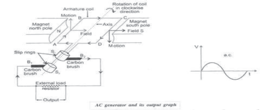
At this instant arm AB is moving up and CD is moving down. After half rotation, arm AB starts moving down while CD moves up. Hence the direction of current in the coil reverses. Net induced current flows in the direction DCBA. Hence, the current in the external circuit now flows from B1 to B2.
Therefore, the polarity of induced current between the brushes B1 and B2 changes after half rotation.
Such current is called alternating current.
33. DC Generator: It generates the current which does not change its direction with time i.e., unidirectional current called direct current. Only difference with AC generator is that in place of slip rings, a split-ring type commutator is used. It consists of two halves, R1 and R2 of a metallic ring which are connected to the two ends of the armature coil as shown in figure.

Working of DC Generator: When armature coil ABCD is made to rotate in a magnetic field, the number of field lines associated with it changes. Hence according to Fleming’s Right-hand rule, the direction of current in the arms of a coil reverses after every half rotation. With the help of split rings type commutator one brush is at all times in contact with the moving down. With this arrangement an induced unidirectional current always flows from B1 to B2 in the external circuit. Such current in the external circuit is called direct current.
34. Alternating Current (AC): The current which changes direction after equal intervals of time i.e., the current which reverse the direction periodically is called alternating current.

The current or voltage – time graph for alternating current is shown in figure.
In India, the frequency of AC is 50 Hz. It means AC changes direction after every 1/100 second i.e., after every 1/100 sec. current changes its polarity.
The circuit symbol for alternating current is
35. Direct Current (DC): The current which flows consistently in one direction is called direct current.
The voltage or current-time graph for direct current is shown in figure.
• Direct current is obtained from batteries, solar cells, D.C. generator.
• Direct current is used in
I. Charging the batteries
II. Nearly in all electronic systems as the source of power supply
III. The production of aluminium
IV. The electrochemical process.

36. Advantages of AC over DC:
I. The generation of AC is cheaper than that of DC.
II. AC voltage can be stepped up or stepped down with the help of transformers.
III. The magnitude of AC can be controlled by using inductor (coil) without any appreciable loss of energy.
IV. AC can easily be converted into DC with the help of rectifiers.
V. AC can be transmitted over a long distance without much loss of energy as compared to a DC transmission.
VI. AC devices are highly efficient, more durable, less expensive and simple in their function.
37. Disadvantages of AC:
I. It is dangerous to use due to its high peak value. So better insulation is required.
II. As AC is transmitted over the surface of a conductor, it needs several strands of thin wire insulated from each other.
III. Any electrical equipment which needs DC cannot run on AC.
IV. At higher voltage of AC, more safety measures are required.
V. AC attracts persons who touch it unlike DC which gives a repelling shock. So AC is more dangerous as compared to DC.
38. Disadvantages of DC:
I. When DC is transmitted over a large distance, a large amount of power is lost due to resistance of the wire.
II. Direct current must be generated at the voltage required at the consumer level.
39. Domestic Electric Circuits: The power distribution companies supply alternating current (AC) for the domestic purposes. As the direction of AC changes periodically, the two separate insulated wires namely live and neutral wire are used for this purpose.
In India, live wire is maintained at 220 V, while the neutral is at 0 V. So, a potential difference of 220 volts is maintained across these two wires. In addition to these wires, a third wire called earth wire is also used in domestic circuits as a safety measures.
The colour convention of insulation on these wires is given below:
I. Live (phase) wire – Red (or brown)
II. Neutral wire – Black (or blue)
III. Earth wire – Green (yellow)
The live and neutral wires are connected to a meter which measures the consumption of electrical energy in kilowatt hours (kWh) (equal to one unit) consumed by various electrical appliances, connected in parallel.
Generally two separate circuits are used for various purposes in our homes. These are lightning circuit and power circuit.
Lightning Circuit: The circuit which is used for low power rating devices such as bulbs, tube lights, fans, T. V., computer, etc. having a current rating of 5A is known as lightning circuit.
Power Circuit: The circuit which is used for high power rating devices such as microwave oven, air conditioners, geysers, washing machine, etc. having a current rating of 15A is known as power circuit.
Lightning circuit and power circuit bot have :
live wire , red insulation at 220 v ; Neutral wire ,black or blue insulation at zero volt.
Earth wire , green or yellow insulation.
40. Earthing: The arrangement of connecting the metallic body (casing) of an electrical device to a copper plate buried deep in the earth near the house is called earthing and the connecting wire is called earth wire.
Functions of Earth Wire: The earth wire
I. Provides low resistance path to the leakage current.
II. Keeps the potential of metallic body of and electrical appliances equal to that of ground i.e., at zero potential.
Necessity of Earthing: Any leakage of current in an electrical appliance to their metallic body is immediately transferred to the Earth through the earth wire and user gets protected from possible and dangerous electrical shock.
Hence, it is necessary to ground the metallic appliances through the earth wire which acts as a safety measure.
41. Short Circuit: When resistance of the circuit becomes very small without connecting any extra load, a large amount of current flows through it, the circuit is said to be short-circuited.
I. Failure of electrical insulations due to which live wire comes in direct contact with neutral or earth wire.
II. Presence of external conducting material (such as water) that is introduced accidently into the circuit.
III. Electrical appliances are forced to operate when its moving parts are jammed.
IV. Connection of current carrying parts of electrical equipment to one another due to human or natural cause or
V. Use of less rating wires.
When this happens, there is an excessive electric current which can damage the circuit and may also cause electrical fires.
42. Overloading: If the current drawn by the many electrical appliances connected to a single socket exceeds the current rating of the wire, the entire circuit or part of circuit gets heated and can even cause fire. This is known as overloading. It might be due to
I. Accidental hike in supply voltage or
II. Connecting too many appliance to a single socket or
III. Damage in the insulation of wires or
IV. Same fault in the appliances or
V. Direct contact between a live wire and a neutral wire.
43. Protection of Circuit:
Safety devices which can be used to prevent short circuit by two methods
a) Earth wire
b) Fuse wire
The use of electric fuse, most important safety device, in series with live wire prevents the electrical appliances and circuits from the possible damage due to the short circuiting or overloading of the circuits.
It is based on heating effect of current
It has low melting point and high resistivity.
According to Joule’s law of heating, when current passing through fuse wire exceeds its maximum limit, a large amount of heat is produced which melts the fuse wire and stops the flow of current through the circuit. This saves the appliances from possible damage.
Earth wire is connected between ground and metallic body of an appliances .It maintains the metallic body at zero potential hence the user gets protected from electric shock.