Exam Question for Class 10 Science Chapter 12 Electricity
Please refer to below Exam Question for Class 10 Science Chapter 12 Electricity. These questions and answers have been prepared by expert Class 10 Science teachers based on the latest NCERT Book for Class 10 Science and examination guidelines issued by CBSE, NCERT, and KVS. We have provided Class 10 Science exam questions for all chapters in your textbooks. You will be able to easily learn problems and solutions which are expected to come in the upcoming class tests and exams for standard 10th.
Chapter 12 Electricity Class 10 Science Exam Question
All questions and answers provided below for Exam Question Class 10 Science Chapter 12 Electricity are very important and should be revised daily.
Exam Question Class 10 Science Chapter 12 Electricity
Very Short Answer Type Questions:
Question: Why does a compass needle get deflected when brought near a bar magnet?
Answer.A compass needle behaves like a small bar magnet when it is brought near a bar magnet. Its magnetic field lines interact with that of bar magnet. Hence compass needle gets deflected.
Question: Why don’t two magnetic lines of force intersect each other?
Answer.No two magnetic field lines intersect each other because if they did, it would mean that at the point of intersection, the compass needle would point towards two direction, which is not possible.
Question: A current through a horizontal power line flows from east to west direction. What is the direction of magnetic field at a point directly below it and at a point directly above it?
Answer.At a point below it, the direction is from North to South and at a point above it, the direction is from South to North.
Question: If in a straight wire ‘A’, current is flowing in vertically downward direction whereas in the straight wire ‘B’ current is flowing in vertically upward direction. What is the direction of magnetic field (a) in wire ‘A’, (b) in wire ‘B’.?
Answer.(a) Anticlockwise, (b) Clockwise
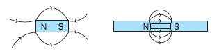
Question: A bar magnet is placed between two iron bars. Draw a diagram to show the induced poles.
Answer.Both the iron bars get magnetised as shown in the figure

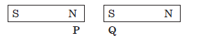
Question:6. Identify the poles of the magnet as shown in the given figure:
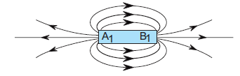
Answer.A1 represents North pole and B1 represents South pole.
Question: State the direction of magnetic field inside a bar magnet.
Answer.It is from South pole to North pole.
Question: Mention the special feature regarding the shape of magnetic field lines.
Answer.Magnetic field lines are closed curves.
Question: If magnetic field lines are crossed at a point, what does it indicate?
OR
Explain why two magnetic lines of force do not intersect.
Answer.The magnetic lines of force do not intersect with each another due to the fact that resultant force on the north pole at any point can only be in one direction. But if the two magnetic lines of force intersect one another, then the resultant force on the north pole placed at the point of intersection will be along two directions, which is not possible.
Question: Draw a diagram to represent the uniform magnetic field in the region around the magnet.
Answer.

Question: What type of core is used in electromagnets?
Answer.Soft iron core.
Question: Draw the magnetic field lines around a straight current carrying conduction.
Answer.
Question: Define the term electrical resistivity of a material.
Answer: Electrical resistivity is defined as the electrical resistance of a conductor having cross-sectional area 1 m2 and length 1m.
Question: What will happen to the resistivity of a wire of length L if it is cut into three parts?
Answer: Resistivity of the wire will not change even when the wire is cut into three parts as resistivity is a characteristic of the material of the conductor and does not depend on the physical dimensions of the conductor.
Question: How will the heat produced in a resistor R change if its resistance is reduced to half of its initial value, other parameters of the circuit remain unchanged?
Answer: The heat produced in a resistor R is given by Joule’s law of heating H = I2Rt, where I is the current and t is the time. When R becomes R/2, I will become 2I according to Ohm’s law.
Therefore, heat produced = (2I)2(R/2)t = 2H.
The heat produced will become double.
Question: Find the minimum rating of fuse that can be safely used on a line on which two 1.1 KW electric geysers are to run simultaneously.
The supply voltage is 220 V.
Answer: Power P = VI. As the two geysers have power
rating 1.1 kW or 1100 W and are connected in parallel, each geyser draws a current I = P/V = 1100/220 A =5 A.
Therefore, total current drawn = 10 A, which should be the minimum rating of fuse that can be safely used.
Question: The potential difference across the wire having fixed resistance is tripled. By how much does the electric power increase?
Answer: The electric power will increase by nine times when the potential difference across the wire having fixed resistance is tripled. According to Ohm’s law, potential difference V is proportional to current, I. Therefore, when V is made 3 times, I will increase 3 times. As Power P = VI, therefore, Power will increase by 9 times.
Question: Define resistance. Give its S.I. unit.
Answer: Resistance is the property of a conductor to oppose the flow of charges through it. SI unit of resistance is Ohm (Ω).
Question:The voltage-current (V-I) graph of a metallic conductor at two different temperature T1 and T2 is shown. At which temperature is the resistance higher.

Answer: Resistance is the slope of VI graph. The slope of graph at T2 > slope of graph at T1. Therefore, resistance is higher at T2.
Question: Should the resistance of an ammeter be low or high? Give reason.
Answer: An ideal ammeter is one which has zero resistance. But that is not possible. Therefore, the resistance of an ammeter should be as
close to zero as possible. If it is non-zero and substantial, it will affect the current flowing through the circuit.
This is because an ammeter is connected in series in the circuit for the measurement of electric current.
Question: The temperature of the filament of bulb is 2700C when it glows. Why does it not get burnt up at such high temperature?
Answer: Filament of bulb is made using strong metals having high melting points such as Tungsten which has melting point of 3380 0 C, which is higher than the temperature at which it glows.
Short Answer Type Questions:
Question: What are magnetic field lines? How is the direction of magnetic field at a point deter- mined?
Answer.(i) The magnetic field lines produced is into the plane of the paper at R and out of it at S. 1
(ii) Field at S > Field at P
Magnetic field strength for a straight current carrying conductor is inversely proportional to the distance from the wire. 2
(iii) The current will be going from top to bottom in the wire shown and the magnetic field lines are now in the clockwise direction on the plane which is perpendicular to the wire carrying current. 1
(iv) Right hand thumb rule. The thumb is aligned to the direction of the current and the direction in which the fingers are wrapped around the wire will give the direction of the magnetic field.
Question: Describe an activity to determine the direction of magnetic field produced by a current carrying straight conductor. Also show that the direction if the magnetic field is reversed on reversing the direction of the current.
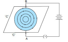
Answer.(i) Take a straight vertical wire AB passing through a horizontal cardboard ‘C’.
(ii) The ends of wires are connected to a battery and a switch.
(iii) When the current is passed through the wire AB, it produces a magnetic field around it, which can be shown by sprinkling iron filings on the cardboard ‘C’.
(iv) The iron filings get magnetised and arrange themselves in concentric circles around the wire.
(v) It shows that magnetic field of lines are circular in nature.
(vi) When current passed in the wire it flows in upward direction, the lines of force are in anticlockwise direction.
(vii) Now pass current from B to A, i.e. in downward direction, the magnetic lines of force will be clockwise.
Question: Draw magnetic field lines around a bar magnet.
Answer.
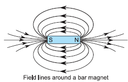
Question: What are magnetic field lines? Explain why magnetic field lines are closed curves?
Answer.The closed path traced by the unit North pole (imaginary) in a magnetic field are called magnetic field lines.
They are continuous closed curves because they diverge from the north pole of a bar magnet and converge to its south pole.
Question: The given magnet is divided into three parts A, B and C as:
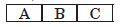
Name the part when the strength of magnetic field is (i) maximum, (ii) minimum. How will the density of magnetic field lines differ at these parts?
Answer.(i) Maximum of magnetic field strength is at ‘A’ and ‘C’
(ii) Minimum of magnetic field strength is at ‘B’.
At ‘A’ and ‘C’ magnetic field lines are crowded whereas these are spread out at ‘B’.
Question: A compass needle is placed near a current-carrying wire. State your observation for the following cases, and give reason for the same in each case.
(a) Magnitude of electric current in the wire is increased.
(b) The compass needle is displaced away from the wire.
Answer.(a) Observation: The compass needle is deflected more.
Reason: Current carrying wire produces magnetic field, (B μ I).
(b) Observation: The deflection of magnetic needle decreases.
Reason: The strength of magnetic field decreases with increase in distance from the wire. (B∝1/2)
Question: (a) Two magnets are lying side by side as shown below. Draw magnetic field lines between the poles P and Q:
(b) What does the degree of closeness of magnetic field lines near the poles signify?
Answer.(a) Magnetic field lines are shown below:
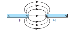
(b) It shows that magnetic field is stronger near the poles, i.e. the pole of another magnet when placed in the magnetic field of a magnet will experience greater force. That is why field lines are crowded.
Question: Magnetic field lines of two magnets are shown in figure A and figure B
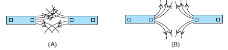
Select the figure that represents the correct pattern of field lines. Give reasons for your answer. Also name the poles of the magnets facing each other.
Answer.
Figure ‘B’ represents correct pattern of magnetic field lines because magnetic field lines never intersect each other. If these intersect there will be two directions of the magnetic field at the point of intersection, which is not possible. In figure B. field lines are emerging (going away) from the magnet,so both the poles are north poles.
Question: Identify the poles of the magnet in the given figure (1) and (2).
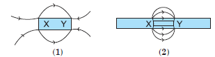
Answer. Field lines emerge from North pole and merge at South pole (S). So, X represents North pole and Y represents South pole.
Question: The magnetic field associated with a current carrying straight conductor is in anticlockwise direction.
If the conductor was held along the east-west direction, what will be the direction of current through it? Name and state the rule applied to determine the direction of current.
Answer.When the observer observes the direction of magnetic field from west then the direction of current is from east to west and if observer is at east side then the direction of current is from west to east.
Right hand thumb rule: If we hold a current carrying conductor in our right hand in a such a way that stretched thumb is along the direction of the current, then curls of fingers around the conductor represents the direction of magnetic field lines.
Question: (a) In a pattern of magnetic field lines due to bar magnet, how can the regions of relative strength be identified?
(b) Compare the strength of magnetic field near the poles and the middle of a bar magnet.
Answer.(a) The closeness of lines measures the relative strength of magnetic field.
(b) The strength of magnetic field is highest near the poles whereas minimum in the middle of bar magnet.
Question: (A) Write the mathematical expression for Joule’s law of heating.
(B) Compute the heat generated while transferring 96000 coulomb of charge in two hours through a potential difference of 40 V.
Answer: (A) Mathematical expression for Joule’s law of Heating:
H = I2Rt
Joule’s law of heating implies that heat produced in a resistor is:
(i) directly proportional to the square of Current.
(ii) directly proportional to the resistance for a given current.
(iii) directly proportional to the time for which current flows through the resistor.
(B) Given Q = 96000 C
t = 2h
V = 40 V
Current I = Q/t
I =96000/2 × 3600
(∴ 1 hour = 60 × 60)
I = 40/3 A
By applying Ohm’s law, we now calculate resistance
R = V/I
R = 40 X 3/40 = 3 W
Heat Produced H = I2Rt
H =(40/3)2X3X2X60X60
=40/3X40/3X3X2X60X60
=11520000/3
or =3,840,000 j
3840 kj
The heat produced is 3840 kJ Alternate method
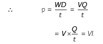
H = Power × Time = V × I × t = V ×(Q/t) xt
V × Q = 40 × 96000 J = 3840000 J
= 3840 kJ
Question: What is the commercial unit of electrical energy? Represent it in terms of Joules.
Answer: The commercial unit of electric energy is kilowatt hour (kW h), commonly known as ‘unit’.
1 kW h = 1000 watt × 3600 second
= 3.6 × 10⁶ watt second
= 3.6 × 10⁶ joule (J)
Question: Which one of the following is the correct set- up for studying the dependence of the current on the potential difference across a resistor
and why?

Answer: Set up A is correct.
The voltmeter should be connected in parallel to the resistor across which potential difference is to be measured and ammeter should be connected in series.
The Positive terminals of voltmeter and ammeter should be connected to the positive terminal of source voltage.
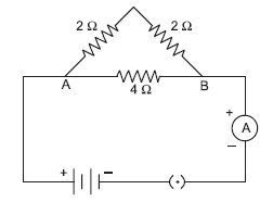
Question: Four resistors of 2 W each are joined end to end to form a square ABCD. Calculate the equivalent resistance of the combination between any two ad??acent corners.
Answer: The circuit diagram will be:
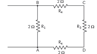
Let us consider the equivalent resistance between points A and B.
Here, three resistances R2(BC), R3(CD), R4(DA) of 2 ohm each are in series, and this combination is connected in parallel across the resistor R1 of
2 ohm(AB) (R1 = 2 ohm)
Equivalent resistance of the three series resistors,
R’ = R2 + R3 + R4
= 2 + 2 + 2 = 6 ohms
Thus, required equivalent resistance (R)
1/R=1/R1+1/R’=1/2+1/6=4/6
R=1.5 ohm.
Question: A V-I graph for a nichrome wire is given below. What do you infer from this graph? Draw a labelled circuit diagram to obtain such a graph.
Answer: We infer from the graph that V/I is a constant ratio. i.e., V a I which is ohm’s law. This constant ratio [V/1] is called the resistance (R) of the conductor.
In 1827, a German physicist G. Siman Ohm found out the relationship between the current (I). Flowing in a metallic wire and the potential difference across its terminals.
The potential difference (v) across the ends of a given metallic wire is in an electric circuit is directly proportional to the current flowing through it, provided its temperature remains the same.
V a I
V/I = Constant
V = IR
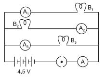
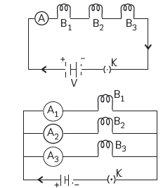
Question: B1, B2 and B3 are three identical bulbs connected as shown in the figure. When
all the three bulbs glow, a current of 3A is recorded by the ammeter A.
(i) What happens to the glow of the other two bulbs when bulb B1 gets fused?
(ii) What happens to the reading of A1, A2, A3 and A, when bulb B2 gets fused?
(iii) How much power is dissipated in the circuit when all the three bulbs glow together?
Answer: Let Req be the net resistance of the combi- nation of three bulbs in parallel, then,
Req = V/1 = 4.5/3 = 1.5 Ω
All bulbs are identical, so they must have the same resistance.
Let R be the resistance of each bulb and all bulbs are connected in parallel, hence,
1/Req= 1/R +1/R+1/R
1/Req=3/R
R=3XReq
= 3 X 1.5 = 4.5Ω
Current flowing across each bulb,
I = V/ R = 4 .5/4.5 = 1 A
Current through each bulb:
(i) If B1 gets fused, the current in B2 and B3 will remain unaffected, as voltage across bulbs B2 and B3 remains the same. Hence, glow of the other two bulbs will not be affected.
(ii) When bulb B2 gets fused, the current through B2 will be zero and the current in B1 and B3 will remain 1A.
Now, net current,
A = A1 + A2 + A3
= 1 + 0 + 1 = 2A
Thus, current in ammeter, A1 = 1 ampere
Current in ammeter, A2 = 0
Current in ammeter, A3 = 1 ampere
Current in ammeter, A = 2 ampere.
(iii) Power dissipated when all three bulbs glow together,
P = V X I
P = 4.5 × 3 = 13.5 W
Alternate method: Power dissipated,
P=V2/Reg=(4.5)2/1.5=13.5W
P = 13.5 W
Question: Two bulbs having power of 50 W and 25 W respectively are connected with the same source. Which has higher resistance? What is their ratio?
Answer: P = V2/R
R = V2/p
We have P1 = 50 and P2 = 25
∴ R1 = V2 / 50 ohm
R2 = V2/25 ohm =1/ 2 ohm
R1 =1/ 2 R2 ohm
i.e., 50 W bulb has 1/2 resistance than 25 W.
Question: Suppose your parents have constructed a two room house and you want that in the living 3 room there should be a provision of one electric bulb, one electric fan, a refrigerator and a plug point for appliances of power up to 2 kilowatt. Draw a circuit diagram showing electric fuse and earthing as safety devices.
Answer:
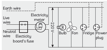
(i) Four components should be labelled.
(ii) All of them should be in parallel and there should be a fuse for safety.
(iii) Live and earth wires should be there.
(0.5 mark to be deducted if all parts of the diagram are not labelled)
Question: Why is parallel arrangement used in domestic wiring?
Answer: Parallel arrangement is used in domestic wiring due to the following reasons:
• Each device will have the same voltage which is equal to the voltage of the supply.
• If two or more devices are used at the same time, then each appliance will be able to draw the required current.
• If one of the devices fails, then the other keeps working.
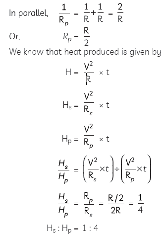
Question: Two conducting wires of the same material and of equal lengths and equal diameters are first connected in series and then in parallel in a circuit across the same potential difference.
Find the ratio of heat produced in series and parallel combination.
Answer: The two conducting wires are of same material, same lengths and diameters. Therefore, their resistances will also be equal.
Let the resistance in each wire be R.
So in series, Rs = R + R = 2 R
Question: (A) Draw a diagram to show how two resistors R1 and R2 should be connected so that the total resistance of the circuit is minimum.
(B) In a circuit, if two resistors of 4Ω and 8Ω are connected in parallel, find ratio of current passing through the two resistors.
Answer: (A) Two resistors R1 and R2 should be connected in parallel so that the effective resistance of the circuit is minimum.

Question: (A) State Ohm’s law.
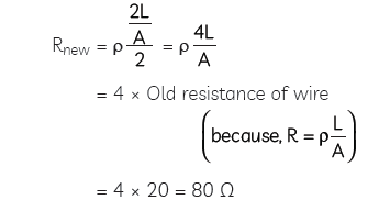
(B) A piece of wire of resistance 20 Ohms is drawn out so that its length is increased to twice of its original length. Calculate the resistance of the wire in the new situation.
Answer: (A) Ohm’s law states that under no same temperature, electric current flowing through an ideal conductor is directly proportional to the potential difference across its ends.
V ∝ I
or V/I == constant = R
or V = IR
R is a constant for the given metallic wire at a given temperature and is called its resistance.
(B) Given R = 20 Ω
Let length of wire is L and when it is drawn out its new length will become 2L.
The volume of wire in both the situations remains constant. So, if the length of wire is doubled, the area of cross section of wire becomes half.
So, the new resistance of the wire,
Question: Answer the following questions:
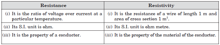
(A) List a distinguishing feature between the resistance and resistivity of a conductor.
(B) A wire is stretched so that its length becomes 6/5 times its original length. If its original resistance is 2?? ohm, find its new resistance and resistivity.
Answer: (A) A distinguishing feature between the
resistance and resistivity of a conductor:
Resistance of a conductor depends on the length and area of cross- section of the conductor. On the other hand, resistivity depends upon the properties of the metal used in conductor. Unit of resistance is ohm and unit of resistivity is ohm-meter.
(B) We know that
R = p 1/A=25
(1) Resistivity of wire is independent of its length or/and area of cross-section. Therefore, increasing the length of wire by 6/5 times results in no change in resistivity.
(2) Where length of wire increases or decreases, the volume of wire remains the same but the area of wire changes as well

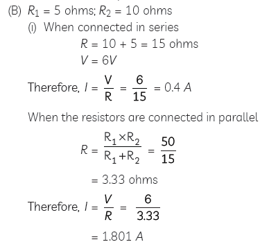
Question: Two resistors with resistance 5 Ohm and 10 Ohm respectively are to be connected to a battery of 6 V so as to obtain:
(A) minimum current flowing
(B) maximum current flowing
(i) How will you connect the resistors in each case?
(ii) Calculate the strength of total current in the circuit in the two cases.
Answer: (A) If we want minimum current, we will connect the resistors in series.
If we want maximum current we will connect them in parallel.
Question: (A) What is the resistance of a conductor?
(B) What happens to the electrical resistance when mercury is cooled to 4.12 k?
(C) What name is given to this phenomenon?
Answer: (A) The property of a conductor due to which it opposes the flow of current through it is called resistance. The resistance of a conductor is numerically equal to the ratio of potential difference across its ends to the current flowing through it.
(B) When mercury is cooled to 4.12 K, the electrical resistance of mercury disappears completely and becomes zero and the mercury becomes super conductor.
(C) This phenomenon of loss of electrical resistance of a substance on cooling it to an extremely low temperature is known as superconductivity.
Question: The values of current I flowing in a given resistor for the corresponding values of potential difference V across the resistor are given below:
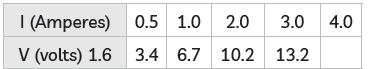
Plot a graph between V and I and also calculate the resistance of that resistor.
Answer: (A) The voltage is plotted on x-axis and current is plotted on y-axis. The values of the current for different values of the voltage are shown in the given table.

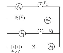
Question: Study the circuit shown in which three identical bulbs B1, B2 and B3 are connected in parallel with a battery of 4.5.V.
(A) What will happen to the glow of other two bulbs if the bulb B3 gets fused?
(B) If the wattage of each bulb is 1.5 W, how much reading will the ammeter
A show when all the three bulbs glow simultaneously?
(C) Find the total resistance of the circuit.
Answer: (A) As the bulbs are in parallel connection, even if bulb B3 gets fused the remaining two bulbs will glow with the same brightness.
(B) Same current flows through all the bulbs as they are connected in parallel.
Total wattage will be added
V = 4.5 V
P = 1.5 W + 1.5 W + 1.5
W = 4.5 W
P = VI
So I = P
V
=
4.5W
4.5 V = 1A
The ammeter reading would be 1 Ampere
(C) Also we know that
V = IR
Therefore R = V/I = 4.5V/1A = 4.5 ohms
Question: Study the following circuit and answer the questions that follows:
(A) State the type of combination of two resistors in the circuit.
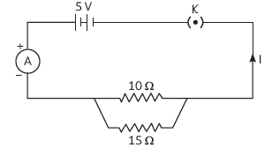
(B) How much current is flowing through (i) 10 ohms and (ii) 1?? ohms resistor?
(C) What is the ammeter reading?
Answer: (A) Resistors in the circuit are connected in parallel combination.

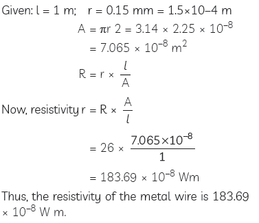
Question: Resistance of a metal wire of length 1 metre is 26 ohms. If the radius of the wire is 0.115 mm, calculate the resistivity of the material.
Answer:
Question: The electric power consumed by a device may be calculated by either of the two expressions
P = I 2R or P = V2/R. The frist expression indicates that it is directly proportional to R whereas the secnd expression indicates inverse proportionality. How can the seemingly different dependence of P on R in these expressions be explained?
Answer: The expression P = I2R is used for calculating electric power when only current I and resistance R are known, whereas P = V2/R is used for calculating power when voltage V and resistance R are known.
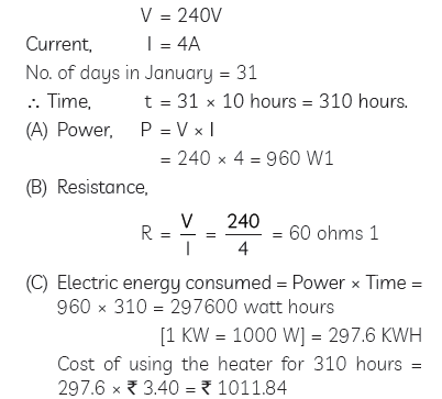
Question: An electric iron is used on a 240 V supply and draws a current of ?? Ampere.
(A) What is its power?
(B) What is its resistance?
(C) What is the cost of using the iron for the month of ??anuary 10 hours a day if 1 KWH costs rupees 3.40?
Answer: An electric iron is used on a 240 V supply and draws a current of 4 Ampere. Therefore, Voltage,
Question: Answer the following:
(A) Why ammeter is always connected in series?
(B) Five dry cells each of 1.?? volt have internal resistance of 0.2, 0.3, 0.??, 0.5 and 1.2 ohms. When connected in series, what current will these five cells furnish through 10 ohm resistance?
Answer: (A) An ammeter is used to measure the current
flowing through a circuit. We know that current remains same in series connection.
Also the resistance of an ammeter is very small due to which it doesn’t affect the current to be measured. So, an ammeter is always connected in series to measure current.
(B) Total voltage produced by the batteries
V = 5 x 1.5 = 7.5 V
Total resistance
R = R1 + R2 + R3 + R4 + R5
R = (0.2 + 0.3 + 0.4 + 0.5 + 1.2) + 10
= 12.6 Ω
Therefore, current
I = V/R =7.5/12.6== 0.595 A.
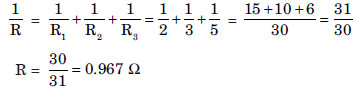
Question: If you connect three resistors having values 2 W, 3 W and 5 W in parallel, calculate the equivalent resistance.
Answer:
Question: B1, B2, B3 are three identical bulbs connected as shown in the figure.
When all the three bulbs glow, a current of 3 A is recorded by the ammeter A.
(i) What happens to the glow of the other two bulbs when bulb B1 gets fused?
(ii) What happens to the reading of A1, A2, A3 and A when bulb B2 gets fused.
Answer:(i) The glow of bulbs B2 and B3 will remain same because they are in parallel connection with bulb B1.
(ii) A1 shows 1 ampere reading, A2 shows zero and A3 show 1 ampere reading. ‘A’ will show 2 A reading.
Question: Redraw the circuit in the above question, putting an ammeter to measure the current through the resistors and a voltmeter to measure the voltage across the 12 W resistor. What would be reading in the ammeter and the voltmeter?
Answer:
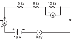
In series combination current in all resistances is same.
Here, I = 0.24 A across 12 Ω resistance
Voltmeter reading, V = IR = 0.24 × 12 = 2.88 V
I = 0.24 A, V = 2.88 V
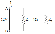
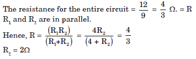
Question: A student has two resistors- 2 W and 3 W. She has to put one of them in place of R2 as shown in the circuit. The current that she needs in the entire circuit is exactly 9A. Show by calculation which of the two resistors she should choose.
Answer:
The overall current needed = 9A. The voltage is 12V
Hence by Ohm’s law V=IR,
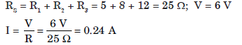
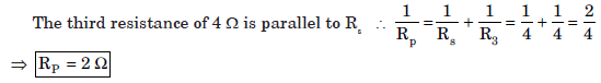
Question:What is (a) the highest, (b) the lowest total resistance that can be secured by combination of four coils of resistances 4 W, 8 W, 12 W, 24 W?
Answer:(a) The highest resistance can be obtained by connecting all resistances in series, i.e.
Rs = R1 + R2 + R3 + R4 = 4 Ω + 8 Ω + 12 Ω + 24 Ω = 48 Ω
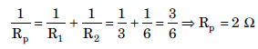
(b) The lowest resistance can be obtained by parallel combination:
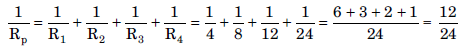
Rp = 2 Ω
Question: Show how you would connect three resistors, each of resistance 6 W, so that the combination has a resistance of (i) 9 W, (ii) 4 W.
Answer:(i) When two 6 Ω resistances are connected in parallel and connected to another 6 Ω in series, we get 9 Ω resistance.
(ii) When two resistors are connected in series and third one is in parallel, we get 4 Ω resistance.
Rs = R1+ R2 = 6 + 6 = 12 Ω
Question: (i) What are the disadvantages of resistances connected in a series circuit?
(ii) Find the resistance between A and B in the following network.
Answer:
(i) Circuit in series vs Circuit in Parallel (Disadvantages of series circuit):
(a) If one electrical appliance stops working due to some factor, then all the other appliances also stop working.
(b) All the electrical appliances have only one switch due to which they can’t turned on or off individually.
(c) The appliances do not get the same voltage as of the input power supply.
(d) Overall resistance increases due to which the current from the input power supply becomes low.
(ii) Two resistances of 2 Ω are in series Rs = R1 + R2 = 2 + 2 = 4 Ω
Question: What are the advantages of connecting electrical devices in parallel combination with the battery rather than in series combination?
Answer:(1) The current required by each device is different which is possible only in parallel combination.
(2) If one device fails others can still work.
(3) Total resistance in the circuit is decreased.
Question: Find the current drawn from the battery by the network of four resistors as shown in the figure.
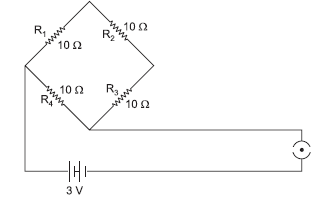
Answer:R1, R2, R3 are in series combination and R4 is in parallel combination to these combination of resistors.
Equivalent resistance of the given network is given as:

Question: Show how would you join three resistors, each of resistance 9 Ω so that the equivalent resistance of the combination is (i) 13.5 Ω, (ii) 6 Ω?
Answer:

Two 9 ohm resistors in parallel combination are connected to one 9 ohm resistor in series;

(ii) Two 9 ohm resistors in series connected are connected to one 9 ohm resistor in parallel;


Question: If three resistors of 6 Ω, 9 Ω and 21 Ω are connected in series to a 12 V battery, find:
(a) The total resistance of the circuit.
(b) The current flowing through the circuit.
(c) The potential difference across the 21 Ω resistor.
Answer:(a) 36 W

(c) V = R × I ⇒ V = 21 × 0.33 = 6.93 V
Question: An electric lamp of 100 W, a toaster of resistance 50 W, and a water filter of resistance 500 W are connected in parallel to a 220 V source. What is the resistance of an electric iron connected to the same source that takes as much current as all the three appliances, and what is the current flowing through it?
Answer:
R1 = 100 Ω, R2 = 50 Ω, R3 = 500 Ω, V = 220 V

Current will remain the same if the electric iron is connected with the same source, i.e.
I = 7.04 A
R = 125/4 = 31.25 Ω across the electric iron.
Question: Study the following electric circuit and find the
(i) current flowing through the circuit and
(ii) the potential difference across 10 W resistor.
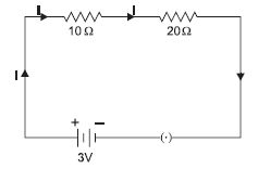
Answer:(i) Rs = R1 + R2 = 10 Ω + 20 Ω = 30 Ω
I =V/R = 3V /30Ω = 0.1
(ii) V = I × R = 0.1 × 10 = 1 V
Question: Figure shows a 2 W resistor and a 6 W resistor connected in series with a 4 V battery. Calculate:

(a) the combined resistance of the resistors.
(b) the current in the battery.
(c) the current in 2 W resistor.
Answer:(a) Rs = R1 + R2 = 2 W + 6 W = 8 W
(b) I =V/R =4/8= 0.5 A
(c) Current across the 2 W resistor = 0.5 A
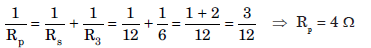
Question: How can three resistors of resistances 2 Ω, 3 Ω, and 6 Ω be connected to give a total resistance of (a) 4 W, (b) 1 W?
Answer:(a) In order to get 4 W resistance, 2 W resistance should be connected in series with a combination of 3 Ω and 6 Ω resistances connected in parallel with each other.
Rs = R3 + Rp = 2 W + 2 W = 4 W
(b) In order to get 1 W resistance all the three resistors should be connected in parallel.


Rp = 1 W
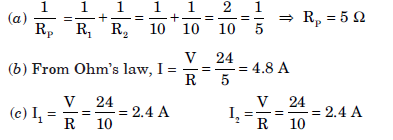
Question: The parallel combination of two 10 W resistors are placed across the terminals of a 24 V battery.
(a) What is the effective resistance of the parallel combination of resistances in the circuit?
(b) What is the current through the entire circuit?
(c) What is the current through each branch of the circuit?
Answer:
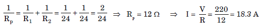
Question: How many 176 W resistors (in parallel) are required to carry 5 A current on a 220 V line?
Answer:When ‘N’ resistors each of resistance ‘R’ are connected in parallel, then Rp =R / N

Question: A hot plate of an electric oven connected to a 220 V line has two coils A and B, each of 24 W resistance, which may be used separately, in series, or in parallel. What are the values of current in the these cases?
Answer:
I =V/R =220/24 = 9.17 A
When coils are used in series, Rs = R1 + R2 = 24 + 24 = 48 W ⇒ I =V/R =220/48 = 4.58 W
When coils are used in parallel
Long Answer Type Questions:
Question:1. PQ is a current carrying conductor in the plane of the paper as shown in the figure below.
(i) Find the directions of the magnetic fields produced by it at points R and S?
(ii) Given r1> r2, where will the strength of the magnetic field be larger? Give reasons.
(iii) If the polarity of the battery connected to the wire is reversed, how would the direction of the magnetic field be changed?
(iv) Explain the rule that is used to find the direction of the magnetic field for a straight current carrying conductor.

Answer.
(i) The Magnetic field lines produced is into the plane of the paper at R and out of it at S.
(ii) Field at S > Field at P
Magnetic field strength for a straight current carrying conductor is inversely proportional to the distance from the wire.
(iii) The current will be going from top to bottom in the wire shown and the magnetic field lines are now in the clockwise direction on the plane which is perpendicular to the wire carrying current.
(iv) Right hand thumb rule. The thumb is aligned to the direction of the current and the direction in which the fingers are wrapped around in wire will give the direction of the magnetic field.
Question: Three incandescent bulbs of 100 W each are connected in series in an electric circuit. In another set, three bulbs of the same wattage
are connected in parallel to the same source.
(A) Will the bulb in the two circuits glow with the same brightness? ??ustify your answer.
(B) Now, let one bulb in both the circuits get fused. Will the rest of the bulbs continue to glow in each circuit? Give reason.
Answer: (A) The two situations given in the question are shown in the figures given below:
For series combination:
Let us assume that the resistance of each bulb is R and the potential difference is V Equivalent resistance in series combination,
Req = R + R + R = 3R.
Let current through each bulb in series combination be I1 and voltage = V
By Ohm’s law,
V = I1 × 3R
I1 = V/3R
The power consumption of each bulb in series combination will be
P1 = I2R
= (I1)2 × 3R = (V/3R) 2 x 3R
= V2/3R
…(i)
For parallel circuit:
The resistance of each bulb = R
Voltage across each bulb = V
[as voltage remains the same in parallel combination]
I1 = V/R
V
Power consumption of each bulb in parallel combination,
P2 = V2/R
…(ii)
From equation (i) and (ii)
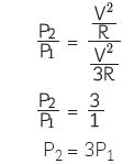
The resistance of the bulbs in series will be three times the resistance of one bulb. Therefore, the current in the series combination will be one-third the current of one bulb in parallel combination.
Therefore, bulbs in parallel combination glows more brighter than each bulb in series combination.
(B) In series combination, there is only one path for the flow of current. So when one bulb gets fused, circuit is broken and hence the bulb stops glowing.
In parallel combination, each bulb has its own path for the flow of current. So when one bulb gets fused, other bulbs will continue to glow as the current is flowing in the circuits of these bulbs.
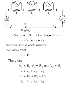
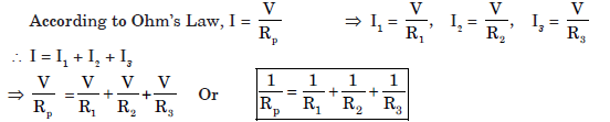
Question:How will you conclude that the same potential difference (voltage) exists across three resistors connected in a parallel arrangement to a battery?
Answer: The same potential difference exists across three resistors connected in a parallel arrangement to a battery can be concluded as follows:
• Take three resistors R1, R2 and R3 and connect these resistances in parallel with a voltmeter, an ammeter, a key and a battery of known voltage as shown in the figure given.
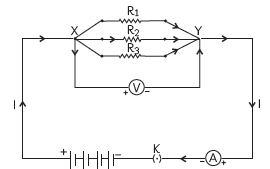
• Plug the key and measure the potential difference when all the three resistors are connected in parallel.
• Open the key and remove the ammeter and voltmeter from the circuit and insert the voltmeter in parallel with R1 and the ammeter in series with the resistor R1, as shown in the figure given below. Again,
the voltmeter and ammeter readings are recorded.
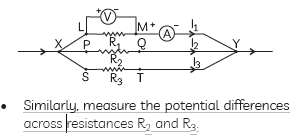
• Similarly, measure the potential differences across resistances R2 and R3.
Observations:
It is observed that the voltmeter shows the same reading in all these conditions. This shows that the voltage or potential difference across each resistor is the same and equal to the potential difference across the combination.
Question: (A) Define electric power. An electrical device of resistance R is connected across a source of voltage V and draws a current I.
Derive an expression for power in terms of current and resistance.
(B) Two electric bulbs rated 100 W; 220 V and 60 W; 220 V are connected in parallel to an electric mains of 220 V. Find the current drawn by the bulbs from the mains.
Answer: (A) Electric Power is defined as the rate at which electrical work is done or the rate at which electrical energy is consumed or dissipated.
Derivation of relation between Power Q,Voltage Q and current I:
Let charge flowing in the circuit be Q in time t.
We know that current I = Q/T .
The work done WD in moving the charge Q through a potential difference V is VQ.
The source must supply energy VQ in time t.
According to Ohm’s law, V = IR.
\ P = VI =(IR)I =I2 R
(b) As the two bulbs are connected in parallel, total current drawn will be sum of currents drawn individually by each bulb.
Let I1 and I2 be the currents drawn by the 100 W and 60 W bulbs respectively.
I1 = P/V= 100/220 A = 5/11A and I2 = 60/220 A=3/1A
Total current drawn = I1 + I2 = 5/11+3/11 =8/11A = 0.72A
Question:Two identical resistors, each of resistance 15 W, are connected in (i) series, and (ii) parallel,in turn to a battery of 6 V. Calculate the ratio of the power consumed in the combination of resistors in each case.
Answer:

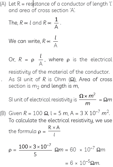
Question:(A) Write the relation between resistanceand electrical resistivity of the material of a conductor in the shape of a cylinder of length ‘l’ and area of cross-section ‘A; Hence derive the S.I. unit of electrical resistivity.
(B) Resistance of a metal wire of length 5 m is 100 W. If the area of cross-section of the wire is 3 × 10⁻⁷ m2, calculate the resistivity of the metal.
Answer:
Question: (A) With the help of a suitable circuit diagram prove that the reciprocal of the equivalent
resistance of a group of resistances Joined in parallel is equal to the sum of the reciprocals of the individual resistances.
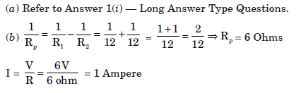
(B) In an electric circuit two resistors of 12 Ω each are ??oined in parallel to a 6 V battery.
Find the current drawn from the battery.
Answer: (A) To prove that the reciprocal of the equivalent resistance of a group of resistances, say 3 resistances, Joined in parallel, is equal to the sum of the reciprocals of the individual resistances.
Consider 3 resistances, R1, R2 and R3 connected in parallel as shown in the circuit diagram.
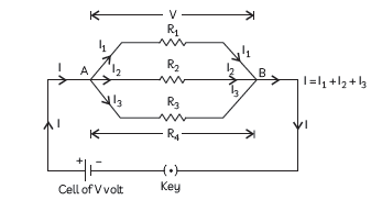
Let the potential difference = V volt and let current flowing through R1, R2 and R3 be I1,
I2 and I3 respectively.
As the resistances are connected in parallel, V will be same across each of the resistances and the total current I is equal to the sum of the currents flowing through each of them.
I = I1 + I2 + I3 ……….(i)
Applying Ohms law to each resistance, we
get I1 = V/R1; I2 =V/R2 and I3 =V/R3 ; ……….(ii)
Also, if R is the effective resistance of the combination of the 3 resistances,
I = V/R ……….(iii)
Using equations (i), (ii) and (iii), we get
V/R=V/R1+V/R2+V/R3
or. 1/R= V/R1+V/R2+V/R3
Hence proved
(b) According to the question, 2 resistors of 12 Ohm each are connected in parallel to a 6 V battery as shown:
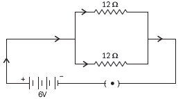
To find the current drawn from the battery, we first need to find the equivalent resistance of the two resistors.
1/R=1/R1+1/R3
or 1/R=1/12+1/12=1+1/12=2/12=1/6
∴ R=6 Ω
According to Ohms law, I =V/R =6/6 == 1 A
Question:What is Joule??s heating effect? How can it be demonstrated experimentally? List its four applications in daily life.
Answer: Joule??s heating effect: When an electric current is passed through a high resistance metallic wire, like nichrome wire, the resistance wire becomes very hot and produces heat. This effect is known as heating effect of current or ??oule’s heating effect.
Joule’s law of heating states that the heat H produced in a conductor of resistance R due to current flowing through it for time t is H = I2Rt
A simple experiment to demonstrate heating effect of current is that if we switch on the bulb for a long period of time then it will become hot. This shows that when electric current flows through a metallic conductor, heat is produced in it.
Applications of Joule’s heating effect in daily life are:
(1) Electric fuse is a safety circuit device works on this principle. Electric fuse in the electric circuit melts when large current flows in the circuit.
(2) Electric iron, electric heater and water heater etc. work on the principle of heating effect of current.
(3) Electric bulb glows when electric current flows through the filament of the bulb.
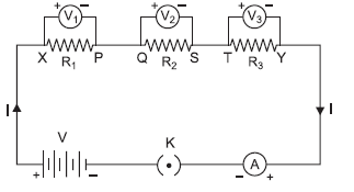
Question:(A) How will you infer with the help of an experiment that the same current flows through every part of the circuit containing three resistors R1, R2 and R3 in series connected to a battery of V volts?
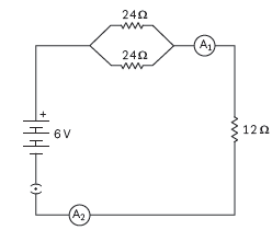
(B) Study the following circuit and find out:
(i) Current in 12 Ω resistor.
(ii) Difference in the readings of A1 and A2, if any.
Answer: (A) (i) Take three resistors R1, R2 and R3 of different values and connect them in series with the help of a battery, ammeter and plug key as shown in the circuit diagram below:

(ii) Plug in the key K and note the reading of the ammeter.
(iii) Change the position of the ammeter to between any of the resistors, say
between R1 and R2, as shown, after taking out the key.

(iv) Plug in the key again and note the ammeter reading.
(v) Repeat steps (iii) and (iv) for different positions of the ammeter.
Observation: We will observe that the ammeter reading remains same no matter
where you connect the ammeter.
Conclusion: This shows that same current flows through every part of a circuit having
three resistors in series connected to a battery.
(B) (i) In the circuit, the two resistors of 24 Ω each are connected in parallel to each
other. The equivalent resistance of the two resistances in parallel is given by
1/Rp=1/ R1+ R2
, where R1 and R2 are the two resistances in parallel.
1/=Rp=1/24 +1/24 =2/24= 1/12
As this combination is in series with the 12 Ω resistance, the total resistance in
the circuit is given by R = Rp + 12 = 12 + 12 = 24 Ω.
Current is given by I = V/R= 6/24 A =0.25A
The current flowing through the 12
Ohm resistance = 0.25 A.
(ii) Since the same current flows through every part of a circuit having resistances
connected in series, both A1 and A2 will give the same reading, 0.25 A
Question: What is electrical resistivity? Derive its SI unit. In a series electrical circuit comprising a resistor made up of a metallic wire, the ammeter reads 100 mA. If the length of the wire is doubled, how will the current in the circuit change? Justify your answer.
Answer: Electrical resistivity is defined as the electrical resistance of a conductor having cross-sectional area 1 m2 and length 1m.
The relation between resistance R, length l, area of cross-section A of an electrical conductor of material having resistivity r is given by R = ρ l/A
Therefore, Rho P = R XA/I .
Putting the SI units of R, A and l in the above formula,
we get SI unit of resistivity =Ω × m2/m = Ω m.
Let V = potential difference and I = Current
flowing in the series electrical circuit = 100 mA.
As Resistance R a 1 ⇒ R will also double when length of the wire is doubled or R becomes 2R.
According to Ohm’s law, V = IR, or, I =V/R ⇒ I
= V/2R=1/2× V/R =1/2× 100mA = 50 mA
Question: An electric lamp of resistance 20 W and a conductor of resistance 4 W are connected to 6 V battery as shown in the circuit. Calculate:
(A) the total resistance of the circuit, (B) the current through the circuit,
(C) the potential difference across the (i) electric lamp and (ii) conductor, and
(D) power of the lamp
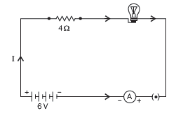
Answer: In the given question, let R1 = resistance of electric lamp = 20 Ohm
Let R2 = resistance of conductor = 4 Ohm.
V = 6 V
The two resistances are connected in series.
(A) The two resistances are connected in series and equivalent resistance of resistors
connected in series is given by R = R1 + R2.
Using the above formula, total resistance of the circuit R = 20 + 4 = 24 Ω.
(B) Current through the circuit is found by applying Ohm’s law.
I = V=R = 6/24 A =1/4 A = 0.25 A
(C) The potential difference across the series combination of resistances is equal to the sum of the potential difference across individual resistance, where V1 is the potential difference across R1 and V2 across R2.
V = V1 + V2
V1 = R1 = 0.25 × 20 = 5V
Similarly, V2 = R2 = 0.25 × = 1V
(D) Power, P of the lamp = V1I = 5 × 0.25 = 1.25 W, where V1 is the potential difference
across the lamp and I is the current flowing through it.
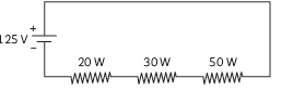
Question: Calculate the total cost of running the following electrical devices in the month of September, if the rate of 1 unit of electricity is ` 6.00.
(i) Electric heater of 1000 W for 5 hours daily.
(ii) Electric refrigerator 1000 W for 10 hours daily.
Answer: The cost of running electrical devices = No. of units consumed X Cost of 1 unit of electricity, where 1 unit of electricity = 1 kWh = 1 kW x 1Hour
To calculate the total cost for the month of September (30 days), we make the following table:

Question: Justify the following statements:
(A) Tungsten is used exclusively for filaments of electric lamps.
(B) Series arrangement is not used for domestic circuits.
(C) Copper and aluminium wires are usually employed for electricity transmission.
Answer:
(A) Due to high melting point/high resistance. (B) In series arrangement, same current will flow through all the appliances which is not required as every appliance needs current of different values. / If one component fails, the circuit is broken and none of the components works.
(C) Good conductors of electricity/ Have low value of resistivity/ Less loss during transmission. (any one)
Question: Resistance determines how much current will flow through a component. Resistors are used to control voltage and current levels. A very high resistance allows a small amount of current to flow and vice versa. In various electrical gadgets, we often we resistors in various combinations and Ohm’s law can be applied to combinations of resistors. Based on above passage and related studied concepts,
answer the following questions.
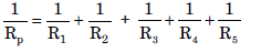
(A) Establish a relationship to determine the equivalent resistance R of a combination of three resistors having resistances R1, R2 and R3 connected in series.
(B) Calculate the equivalent resistance of the combination of three resistors of 2 Ω, 3 Ω and 6 Ω Joined in parallel.
Answer: (A) When two or more resistors are joined end to end, they are said to be connected in series combination. When two or more resist are connected in series, then:
(1) The current through the circuit and also through each resistor remains the same.
(2) The potential difference becomes sum of the individual potential difference across each resistor.
Question: List two distinguishing features between the resistance and resistivity of a conductor. A wire is stretched so that its length becomes 6/5 times of its original length. If its original resistance is 25 W,find its new resistance and resistivity. Give justification for your answer in each case.
Answer:
Since resistance is directly proportional to the length and is inversely proportional to the area of cross section.
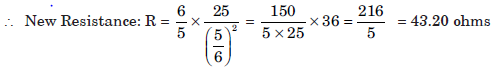
When the wire is stretched, its length becomes 6/5 times of its original length, and area of cross-section will become 5/6. Resistivity will remain the same because it does not depend upon the length and area of cross section. It depends on the nature of material of the substance and the temperature.
Question: You have been assigned a duty to create awareness in your school about saving electricity.
(i) Write any two ways by which you will create awareness among your schoolmates about saving electricity.
(ii) Explain how saving electricity is important at individual level as well as at national level.
Answer:(i) Speaking over it in the morning assembly in school.
• Putting posters over it on the school notice board.
(ii) If we save electricity, it can be used by those villages which do not have electricity.
• It can be used in industries, agriculture and for other useful purposes.
• It improves the national economy because high speed trains, industries, development in villages depends upon electricity.
Question: (i) Write an expression for the resistivity of a substance.
(ii) State the SI unit of resistivity.
(iii) Distinguish between resistance and resistivity.
(iv) Name two factors on which the resistivity of a substance depends and two factors on which it does not depend.
Answer:(i) Resistivity (r) =RA/l
(ii) Its SI unit is W m.
(iii) Resistivity is a characteristic property of a material that does not depend upon the dimensions of the material whereas resistance depends upon the dimensions of the material.
(iv) Resistivity does not depend on the:
(a) length of conductor, (b) area of cross section of conductor
Resistivity depends on the:
(a) nature of material of conductor (b) temperature of conductor
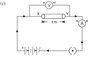
Question: (i) Draw a closed circuit diagram consisting of a 0.5 m long nichrome wire XY, and ammeter, a voltmeter, four cells of 1.5 V each and a plug key.
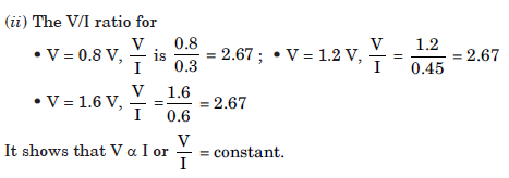
(ii) Following graph was plotted between V and I values:
What would be the values of V/I ratios when the potential difference is 0.8 V, 1.2 V and 1.6 V respectively? What conclusion do you draw from these values?

Answer:
Question: State Ohm’s law. Draw a labelled circuit diagram to verify this law in the laboratory. If you draw a graph between the potential difference and current flowing through a metallic conductor, what kind of curve will you get? Explain how would you use this graph to determine the resistance of the conductor.
Answer:Ohm’s Law: It states that ratio of potential difference and current is constant and is equal to the resistance of the conductor at a particular temperature. In other words, the current flowing through a conductor is directly proportional to the potential difference at a constant temperature.

The graph between V and I will be a straight line.
Slope = tan θ = ‘R’
Slope =BC/AC
= R
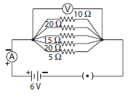
Question: (i) What is meant by series combination and parallel combination of resistances?
(ii) In the circuit diagram given below five resistances of 5W, 20W, 15W, 20W and 10 W are connected as given in the figure to a 6 V battery.
Calculate: (a) Total resistance in the circuit.
(b) Total current flowing in the circuit.
Answer:
(i) Resistors in Series: When resistors are joined end to end, it is called series combination of resistances.
In series combination of resistors, the current remains the same through each resistor. Therefore the value of current in the ammeter remains the same, independent of its position in the electric circuit.
In the above circuit, V is equal to the sum of V1, V2, V3, that is the total potential difference (V) across a combination of resistors in series is equal to the sum of potential differences across the individual resistors.
V = V1 + V2 + V3
The current through each resistor is I.
V = IR
V1 = IR1 V2 = IR2 V3 = IR3
As V = V1 + V2 + V3 ⇒ IR = IR1 + IR2 + IR3 ⇒ RS = R1 + R2 + R3
We can conclude that when several resistors are joined in series, then equivalent resistance of the combination is equal to the sum of their individual resistances and is thus greater than any of the individual resistance.
Resistors in Parallel:
When the resistances, says, R1, R2, R3 are connected in in parallel combination as shown in the diagram, then the potential difference remains the same across each resistor in parallel combination of resistors. In parallel combination the current is distributed in different resistances in different branches.
As, I = I1 + I2 + I3

(ii) (a) Resistance across parallel combination,
Resultant resistance of 5 Ω, 20 Ω, 15 Ω, 10 Ω, and 20 Ω resistances is given as:
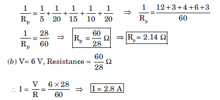
Question: Study the following electric circuit and find (i) the current flowing in the circuit and (ii) the potential difference across the 10 W resistor.
Answer: 10 W and 20 W resistances are connected in series, therefore their equivalent resistance is given by: R1= R1 + R2 = 10 + 20 = 30 W

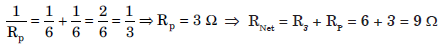
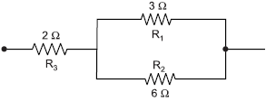
Question: Find the net current flowing through the following electric circuit:
Answer:Series combination of 1 W and 3 W resistance is in parallel combination with 6 W resistor. Their equivalent resistance is

Now, 3.6 W, 2.4 W and 3 W resistors are connected in series, therefore their equivalent resistance be given by: RS = R1 + R2 + R3 = 3.6 + 2.4 + 3 = 9 W

Question: (a) With the help of suitable circuit diagram prove that the reciprocal of the equivalent resistance of a group of resistances joined in parallel is equal to the sum of the reciprocal of the individual resistances.
(b) In an electric circuit two resistors of 12 W each are joined in parallel to a 6V battery. Find the current drawn from the battery.
Answer:
Question: Figure shows a 3 W resistor and a 6 W resistor connected in parallel across a 1.5 V cell.
Calculate the current across: (i) 3 W resistor, (ii) 6 W resistor, (iii) the cell, (iv) calculate the resistance of the parallel combination of 3 W and 6 W resistors.
Answer:

